Beginner Course
Intermediate Course
Advanced Course5. Perfectly Matched LayerThe second-order Mur absorbing boundary condition (ABC) shows good absorption, but it cannot calculate at corners of the numrical grid. Thus, the reflection is increased at the corners and sometimes unstable. In FDTD calculations, the perfectly matched layer (PML) [1] is well known as a highly effective ABC, and excellently absorbs waves even at corners. Modified Maxwell's EquationsThe PML is a pseudo absorptive medium, which surrounds the computational domain with very low reflectivity. Electromagnetic waves entering the absorptive medium exponentially decay and reflect at the outermost perfect conductor, and almost completely absorbed by the time they reach the interior. This pseudo absorptive medium is based on conductive Maxwell's equations, For simplicity, we first consider the two-dimensional Maxwell's equations in the TE mode. 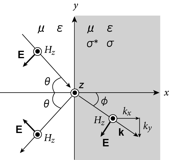 Fig. 1. The plane wave of wave vector k = (kx, ky) impinges upon an absorptive medium in the TE mode. The gray region represents the absorptive medium. θ is the incidence and reflection angle. φ is the refraction angle. When a plane wave impinges the absorptive medium as shown in Fig. 1, the reflection coefficient is given by where θ is the incident and reflection angle, φ is the refraction angle, and Z, Z' are wave impedances in each medium. These impedances are defined by 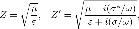 . . . (3) . . . (3)where ω is the angular frequency. When θ = φ = 0, we obtain R = 0 by impedance matching, Z = Z'. Then, the impedance matching condition is given by But when θ ≠ 0 and φ ≠ 0, the impedance matching condition depends on θ and φ. To find an angularly independent impedance matching condition, in the TE mode, we define 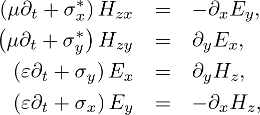 . . . (5) . . . (5)where Hz = Hzx + Hzy. Hzx and Hzy propagate along the x and y axes, respectively. Note that (5) satisfies (1) if σx = σy and σx* = σy*. To find Z', we define a plane wave, (Ex, Ey, Hzx, Hzy) = (-E0sinφ, E0cosφ, H0x, H0y) ei(kxx+kyy-ωt). Substituting the plane wave into (5), we obtain where Thus, the angularly independent impedance matching condition becomes On the other hand, when (8) is satisfied, we find where k = ω/v (v = 1/(με)1/2. Since E⋅T (T = unit vector tangential to the interface) is constant across media interfaces, the phase matching condition satisfies where X and Y are unit vectors along the x and y axes, respectively. The PML is implemented as shown in Fig. 2. 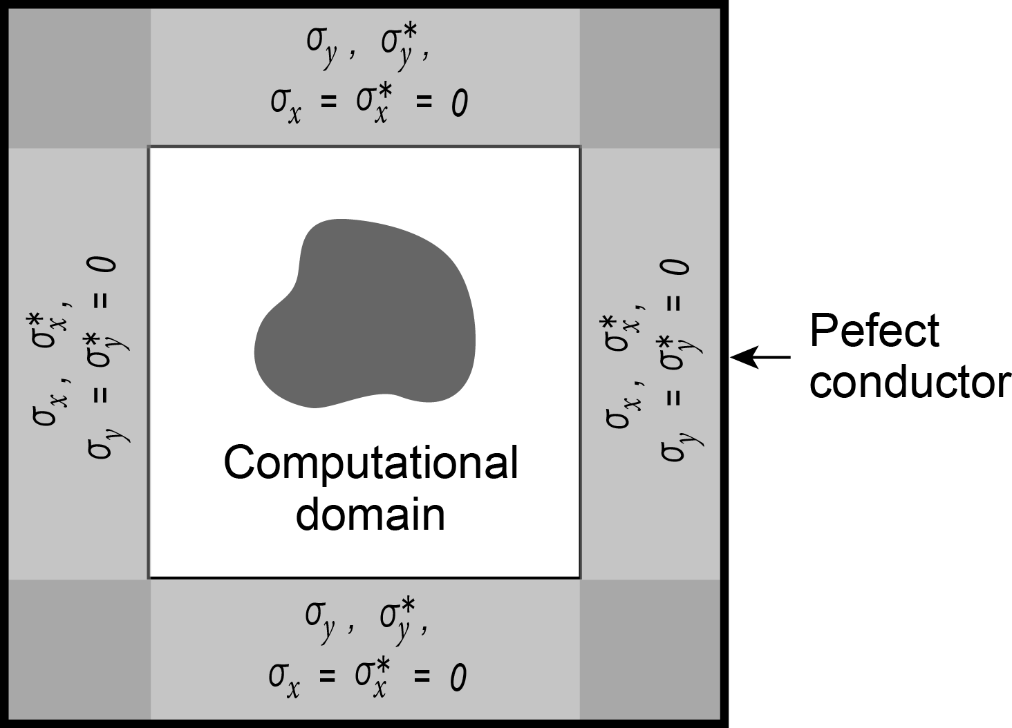 Fig. 2. Layout of the perfectly matched layer. Gray regions represent absorption layers. Outermost layer is the perfect conductor. σx*, σy* are magnetic conductivities. σx, σy are electric conductivities. In the corner domain, σx*, σy*, σx, σy ≠ 0. In the TM mode, conductive Maxwell's equations are separated into 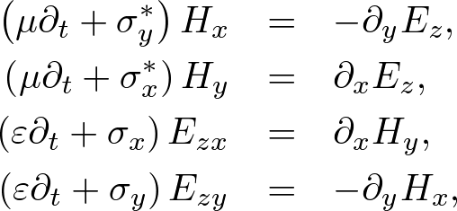 . . . (11) . . . (11)where Ez = Ezx + Ezy. In a similar way to the TE mode, we obtain the same impedance matching condition (8). The three-dimensional PML is given by combining the TE and TM modes. The electromagnetic fields are separated into 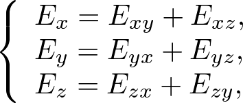 . . . (12) . . . (12)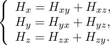 . . . (13) . . . (13)The conductive Maxwell's equations are defined by 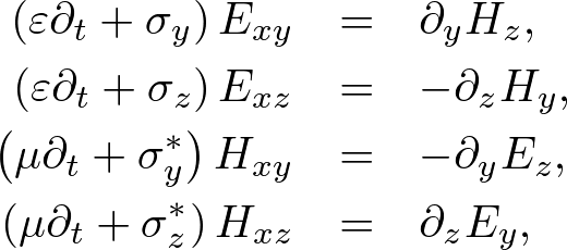 . . . (14) . . . (14)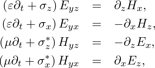 . . . (15) . . . (15)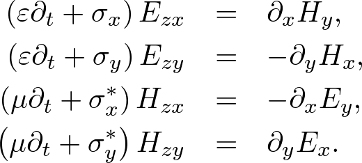 . . . (16) . . . (16)The impedance matching condition is where 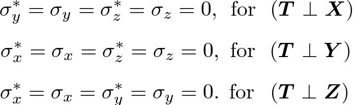 . . . (18) . . . (18)ConductivitiesThe electromagnetic conductivities are discretized on a numerical grid. Let x = 0, h, …, Nxh, y = 0, h, …, Nyh. We define 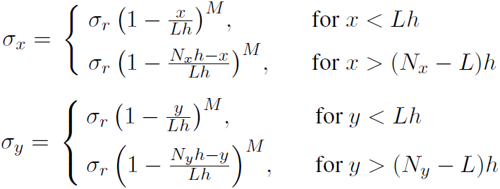 . . . (19) . . . (19)where L is the number of PML layers, M is the damping constant, and σr is given by the reflection coefficient. As shown in Fig. 3, a plane wave must enter into the PML with no reflection and refraction. 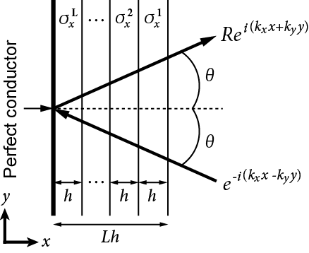 Fig. 3. Reflection in discrete perfectly matched layers. R is the reflection coefficient, L is the number of layers, h is the grid spacing, θ is the incidence and reflection angles. Wavenumber is given by kxn in each layer of conductivity σxn. Since E⋅T is continue across each layers and outermost layer completely reflects the wave, the reflection coefficient becomes where we used (9). If h is sufficiently small, we obtain Since the reflection increases with θ, a value of θ must be fixed in appropriate band of incidence angles. We wish to minimize |R|. If M is set too large, the accuracy of the discrete approximation falls, but if L is too large, the computational cost increases. For example, let the computational girid be difined by (N + 2L)d (d = dimensions). The computational cost increases as Since C2 and C3 exponentially increase, the number of layers must be carefully chosen to achieve the desired accuracy, while minimizing cost. We emprically choose θ = 60°, |R| = 10-8, M = 2, and L = 8.
Bibliography:
Copyright (C) 2011 Naoki Okada, All Rights Reserved.
|