Transformation from reflectance spectrum to BRDFWe transform the reflectance spectrum R into a bidirectional reflectance distribution function (BRDF) under a standard illuminant, using the Commission International de L'Eclairage (CIE) of 1931 XYZ color system transformation [WS82]. We then transform the BRDF from the XYZ color system into the sRGB system. 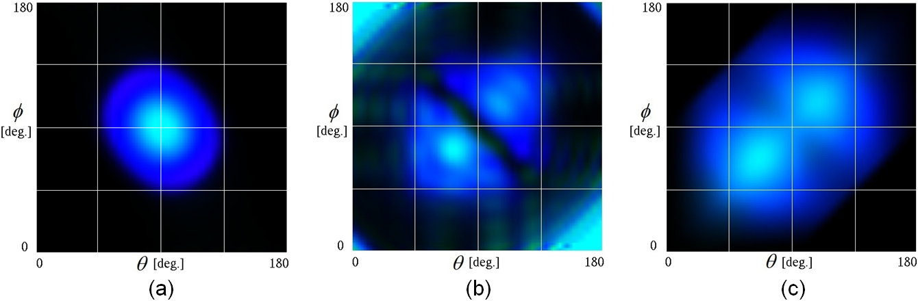 Fig. 1. BRDF color distributions in the sRGB color system: (a) diffraction superposition model for a single ridge (multilayer width = 300nm, interval = 235nm, and number = 10) [KYFO02]; (b) our calculation; and (c) experimental measurement [KZK11] (θ = incidence angle, φ = reflection angle). Figure 1 shows the BRDFs in the sRGB color system, which are given by (a) diffraction superposition model for a single ridge (multilayer width = 300nm, interval = 235nm, and number = 10) [KYFO02]; (b) our calculation; and (c) experimental measurement [KZK11]. The diffraction model fails to capture the backscattering, whereas our result shows good agreement with the measurement. 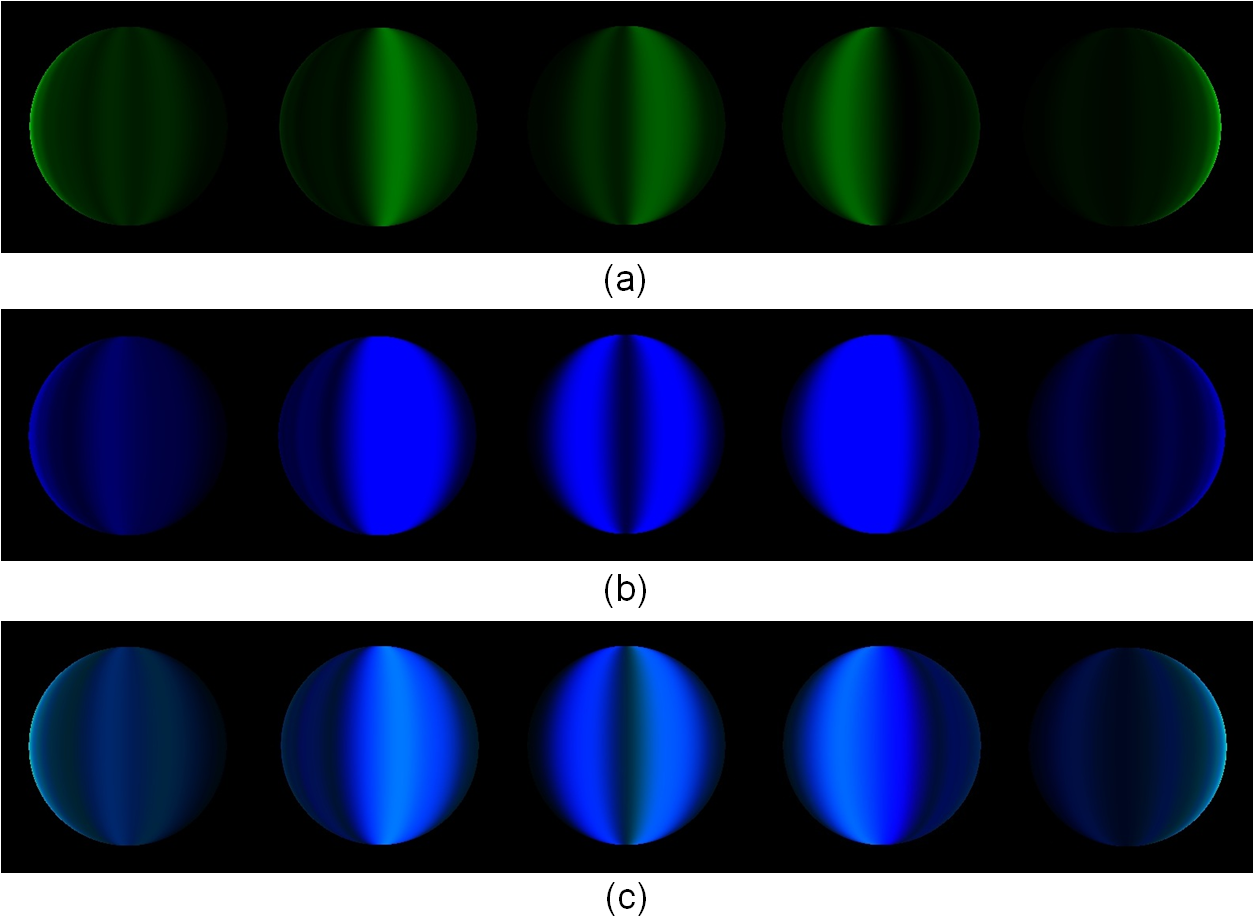 Fig. 2. Rendered color sphere using the simulated BRDF: (a) green; (b) blue; and (c) sRGB. From left to right, the incidence angles are, θ = 30, 60, 90, 120, and 150°, respectively. The observing angle is φ = 90°. Figure 2 shows spheres rendered using the simulated BRDF. The green is reflected over a narrow angle relative to blue (red is almost zero) as shown in Figs. 2(a) and (b). In Fig. 2(c), the brilliant cyan and blue backscattering are captured. Rendering Morpho butterfly CGWe describe how to render male Morpho butterfly CGs using the simulated BRDF. Eliminating spurious transmitted light in the simulated BRDF, we use a simple Lambert shading. The reflected intensity at each surface point is given by where ki is the reflectance, Ii is the incident intensity given in the scene, N is the unit normal vector, and L is the unit incidence vector. In Eq. (1), ki is obtained from the simulated BRDF. The transmitted light is eliminated by the diffusion term, (N·L). 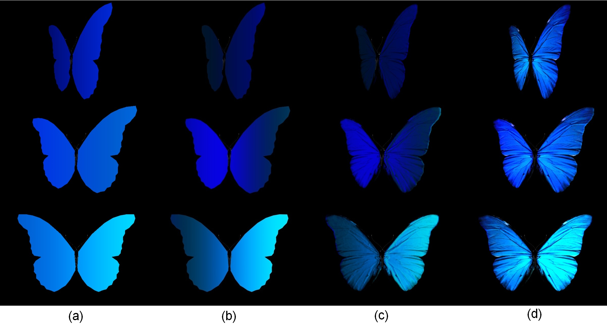 Fig. 3. A male Morpho rhetenor CG using: (a) Experimentally measured BRDF on flat surfaces; (b) Simulated BRDF on flat surfaces; (c) Simulated BRDF on texture- and displacement-mapped surfaces; and (d) Simulated BRDF combined with Morpho wing image. Here the incidence angle is θ = 75°. From up to down, the observing angles are φ = 150, 120, and 90°, respectively.  Fig. 4. (a) Texture of the wing nervule pattern used in the texture- and displacement-mapping. (b) Photograph of the real male Morpho butterfly. Figure 3 displays rendered male Morpho rhetenor images from three different observing angles, among which the incidence angle θ = 75° (the brilliant Morpho blue is strongly reflected). In Fig. 3, rendered images are given by using: (a) the measured BRDF on flat wing surfaces; (b) simulated BRDF on flat surfaces; (c) simulated BRDF on texture- and displacement-mapped surfaces shown in Fig. 4(a); and (d) simulated BRDF synthesized with Morpho wing image. As shown in both Figs. 3(b) and (c), the rendered images capture the backscattering of the brilliant Morpho blue in agreement with experiment shown in Fig. 3(a). We feel, however, that the rendered CG images are monotonous because to create the CG we assumed all ridges and lamellae to be arrayed uniformly in z on the wing surface. In order to show the complicated fuzzy iridescence of real scale distributions on Morpho butterfly wings, we combined the simulated BRDF with wing texture. Figure 4(b) shows the texture photographed using indirect light so that the Morpho blue is mainly given by the simulated BRDF. Figure 3(d) shows the final rendered CG images. 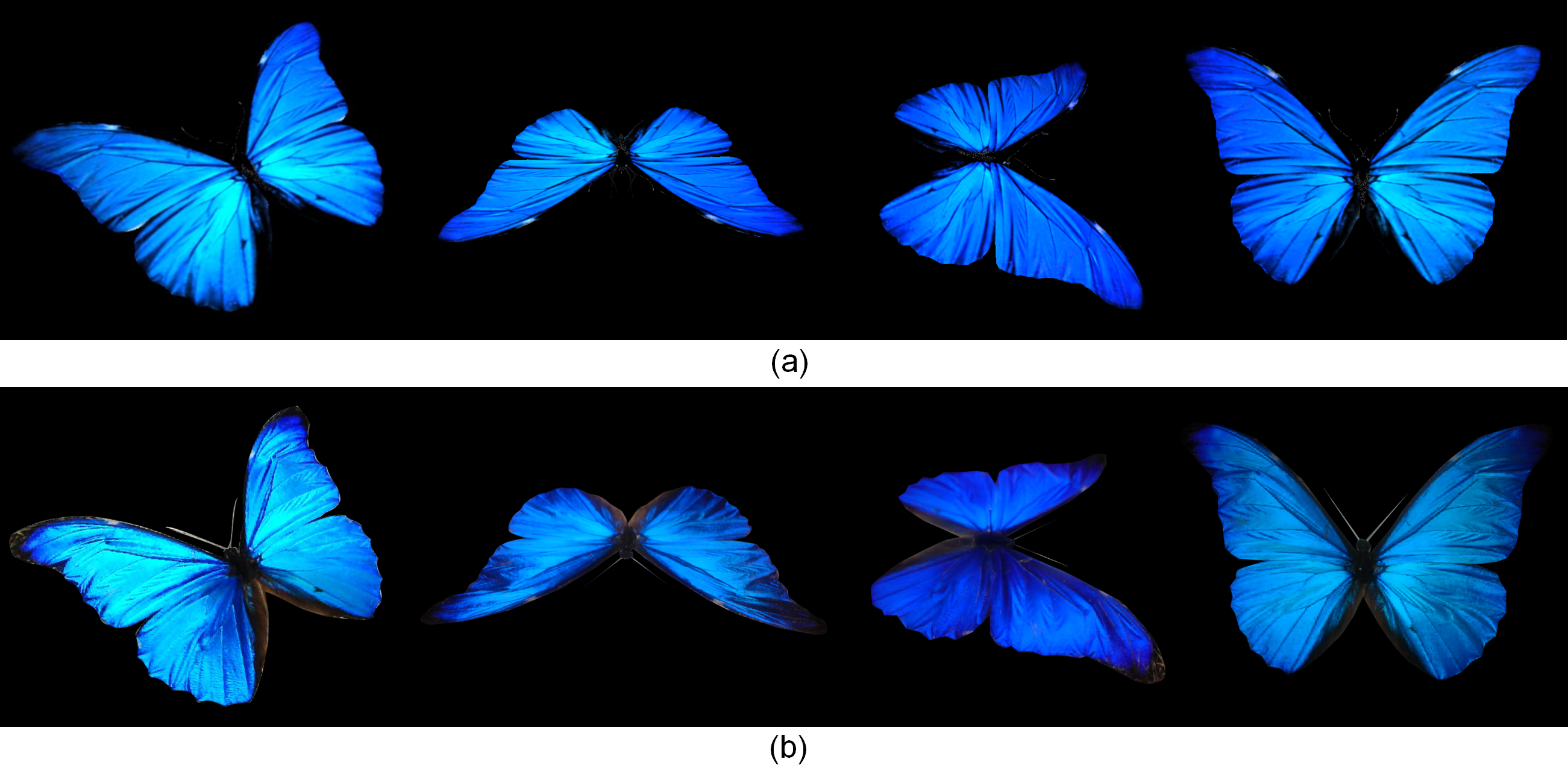 Fig. 5. Comparison of (a) CG images with (b) real photographic images from different observing angles at normal incidence (θ = 90°). In Fig. 5, we compare rendered CG images with photographs from different observing angles. Our results are an improvement over conventional methods [Sun06], and are comparable to photographic images. 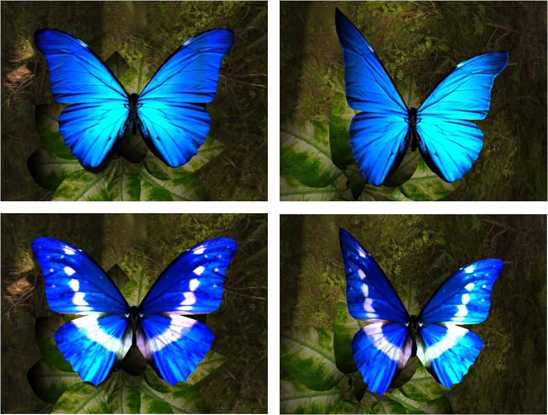 Fig. 6. Rendered Morpho rhetenor butterfly images of Morpho rhetenor (upper) and helena (lower) from different observing angles with a forest background. Finally we render the Morpho rhetenor and helena, which are the same subspecies. The Morpho helena has different wing patterns from that of rhetenor but the nano-structures are almost the same [KYM08]. Figures 6 are rendered images of the Morpho rhetenor and helena from different observing angles with a forest background, and they are comparable to the photographic ones. The CG animation can be seen at YouTube:
Bibliography:
Copyright (C) 2011 Naoki Okada, All Rights Reserved.
|